

10 Tips for Choosing the Right Stocko Connector
Choosing the right Stocko Connector is rarely a simple matter of matching pins and sockets. A connector may fit perfectly on a workbench, yet fail after repeated vibration, heat exposure, or careless installation. The real decision involves current capacity, contact stability, housing material, mounting space, and service conditions.
Connector engineering consultant Dr. Ralf Nägele offers a practical reminder: “A connector is reliable only when its electrical, mechanical, and environmental limits are understood together.” That principle guides this introduction. It also prevents a common mistake: selecting a component from a catalogue image alone. A compact Stocko Connector can look ideal, but its contact force, wire range, and locking method may not suit the final assembly.
Small details matter.
This guide presents ten practical tips for evaluating connector options before production begins. It considers terminal quality, insulation performance, mating cycles, cable routing, and supplier documentation. It also examines how temperature, moisture, vibration, and limited access can influence long-term reliability.
The process is not flawless. Even experienced engineers can overlook assembly pressure or future maintenance needs. A prototype may pass bench testing and still reveal weaknesses during field use. That is why careful comparison, physical testing, and verified technical data remain essential. The best Stocko Connector is not always the smallest or cheapest option. It is the one that fits the application’s real demands, including the uncomfortable details that early designs often ignore.
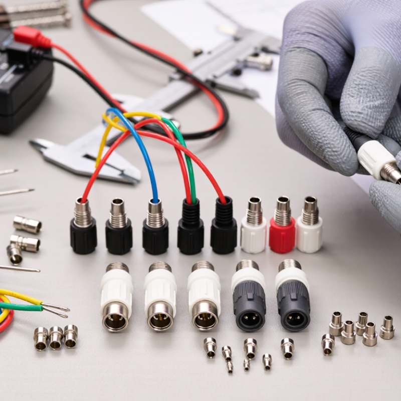
Define the Application Requirements for a Stocko Connector
Choosing the right connector starts with a clear application definition. Do not begin with appearance or price. Record the circuit voltage, continuous current, peak load, wire size, and available space. Peak load matters. A connector rated for normal operation may fail during motor startup. Note whether the housing sits inside a dry panel, near oil, or beside a heat source. These details shape the required material, sealing level, and temperature range.
Map the mechanical conditions before reviewing technical drawings. Measure the panel thickness, mounting direction, mating clearance, and cable bend radius. Decide how often technicians will disconnect the assembly. A rarely serviced joint may need a stronger lock, while a test fixture may favor quick access. Check terminal retention and contact resistance in the technical data. Do not rely on a similar-looking part. Small pitch differences can create costly assembly errors. In production reviews, a simple go/no-go sample often reveals interference that drawings miss.
Define compliance and reliability needs with the whole system in mind. Confirm insulation ratings, flammability data, temperature limits, and applicable regional requirements. Then test a representative assembly under vibration, heat, and expected load. Record results, not assumptions. One weakness is often overlooked: technicians may pull wires instead of housings. Design for that mistake where possible. If the requirement sheet feels vague, it is not ready. Recheck it with assembly and maintenance teams before selecting the final connector.
10 Tips for Choosing the Right Stocko Connector - Define the Application Requirements for a Stocko Connector
| No. | Application Requirement | What to Define | Typical Design Data or Selection Guidance | Priority |
|---|---|---|---|---|
| 1 | Rated Voltage | Identify the maximum continuous voltage, including tolerance, switching events, and possible transients. | A 24 V DC control circuit should be evaluated with the equipment's specified overvoltage and transient conditions, not only the nominal 24 V value. | Critical |
| 2 | Rated Current | Calculate the normal load current, peak current, inrush current, and the number of energized contacts. | Motor, heater, and lamp loads may have starting or inrush currents significantly higher than their steady-state current. | Critical |
| 3 | Contact Configuration | Specify the required number of circuits, poles, contact arrangement, and whether signal and power circuits must be separated. | A control assembly may require separate contacts for supply, feedback, switching signals, protective earth, or auxiliary functions. | High |
| 4 | Connection Method | Determine whether the installation requires crimp, solder, screw, spring, insulation-displacement, or wire-to-board termination. | Spring or insulation-displacement connections can reduce assembly time, while crimp connections are useful for repeatable harness production. | High |
| 5 | Wire and Cable Compatibility | Confirm conductor size, insulation diameter, flexibility, stripping length, and compatibility with solid or stranded conductors. | A connector intended for small control wiring may not accept a larger power conductor or a cable with thick insulation. | Critical |
| 6 | Environmental Conditions | Define operating temperature, humidity, dust, water exposure, chemicals, vibration, and installation altitude. | Outdoor or machinery applications may require environmental sealing, corrosion-resistant materials, and resistance to vibration or thermal cycling. | Critical |
| 7 | Mechanical Stress | Assess insertion and withdrawal frequency, cable pull, bending, shock, vibration, and available mounting space. | A frequently serviced panel may need a connector with suitable mating durability and positive retention to prevent accidental separation. | High |
| 8 | Safety and Insulation | Review insulation requirements, creepage and clearance distances, touch protection, keying, polarization, and locking features. | Higher-voltage circuits require adequate insulation spacing and protection against incorrect mating or accidental contact with live parts. | Critical |
| 9 | Electrical Performance | Check contact resistance, insulation resistance, dielectric withstand, signal integrity, and allowable temperature rise. | Low-level sensor signals benefit from stable contact resistance and suitable shielding or routing practices where electromagnetic interference is present. | High |
| 10 | Compliance and Lifecycle | Identify applicable safety standards, documentation needs, expected service life, replacement strategy, and production volume. | A production design should consider qualification testing, traceability, availability, assembly tooling, and replacement parts throughout the expected equipment life. | Medium |