What Is a Dry Type Transformer and How Does It Work?
A Dry-Type Transformer transfers electrical energy without liquid insulation. Instead, its windings use solid insulation and surrounding air for cooling. This design suits hospitals, commercial buildings, schools, factories, and indoor substations. It reduces concerns about oil leaks and simplifies many installation environments. Still, “maintenance-free” is an unsafe assumption.
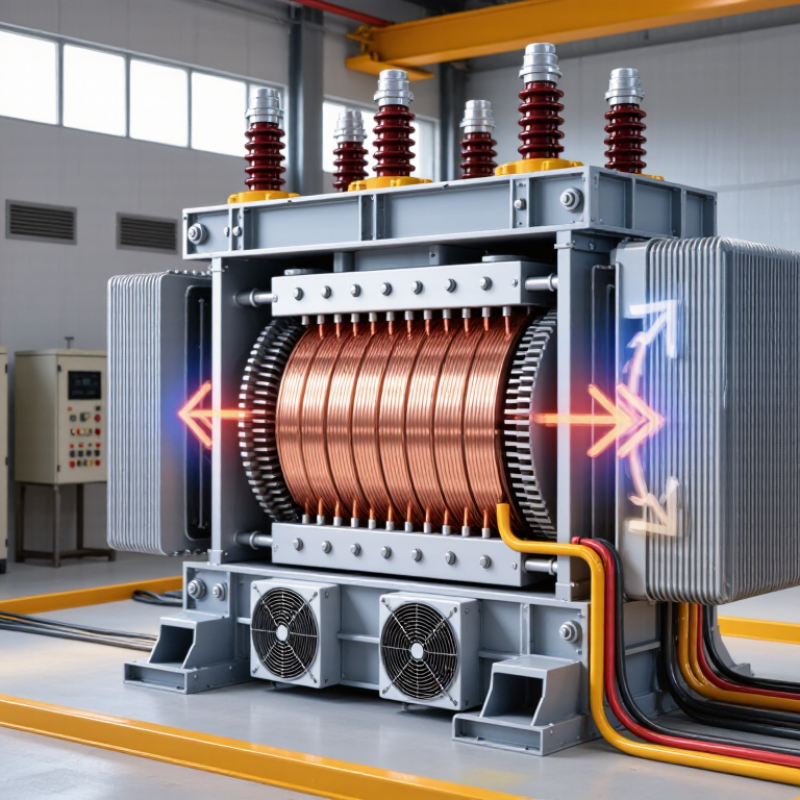
Inside the unit, alternating current enters the primary winding. The magnetic core creates a changing flux. That flux induces voltage in the secondary winding. The transformer changes voltage while keeping the frequency unchanged. Heat then moves from the windings into the air and surrounding enclosure. Fans may assist cooling when the load becomes higher. In a plant inspection, technicians may check dust, cable joints, ventilation paths, noise, and temperature marks. Small details matter.
Reliable performance depends on correct sizing and proper installation. Engineers consider load diversity, ambient temperature, harmonics, enclosure protection, and available fault current. They also follow applicable electrical codes and manufacturer instructions. Standards and testing requirements can vary by region and transformer type. Therefore, a specification should never rely on a generic product description alone. Ask for test records and verified technical data.
This guide explains the main components, operating process, cooling methods, benefits, and limitations of a Dry-Type Transformer. It also examines where this equipment may perform well. The answer is not always simple. A dry design can improve safety in certain spaces, but it may require careful airflow management and regular inspection. Understanding those trade-offs supports safer decisions and longer service life.
Definition and Core Purpose of a Dry Type Transformer
A dry type transformer is an electrical device that transfers alternating current between circuits without using liquid insulation. Its core purpose is clear: it changes voltage levels and provides electrical isolation. This supports safer power distribution in buildings, factories, hospitals, and other indoor facilities.
Inside the enclosure, copper or aluminum windings surround a laminated magnetic core. Alternating current creates a changing magnetic field in the core. That field induces voltage in a separate winding, following electromagnetic induction. The turns ratio determines whether the transformer increases or reduces voltage. Insulation usually relies on air and solid materials, such as resin or treated paper. Heat moves away through natural air circulation or assisted ventilation.
The word “dry” can mislead. It does not mean the unit produces no heat or needs no attention. Dust, blocked vents, loose connections, and excessive loading can raise winding temperatures. In practice, inspection records matter as much as the nameplate rating. A simple explanation also misses one concern: noise may become noticeable in quiet rooms.
Tips: Keep ventilation openings clear and check temperature indicators during operation. Confirm the input voltage, output voltage, frequency, and load before installation. Use qualified electrical personnel for testing, grounding, and maintenance. Small oversights can become costly failures.
Main Components and Their Functions
A dry-type transformer transfers electrical energy without liquid insulation. Its steel core guides magnetic flux and reduces no-load losses. Copper or aluminum windings change voltage through electromagnetic induction. The primary winding receives power; the secondary delivers adjusted voltage. The U.S. Department of Energy’s Distribution Transformer Technical Support Document estimates that U.S. distribution transformers consume about 61 billion kilowatt-hours annually. That figure shows why core and winding efficiency matter.
The core uses laminated electrical steel, limiting eddy-current heating. Winding insulation separates turns and prevents short circuits. In many designs, epoxy resin or varnish reinforces the coils. The insulation also tolerates vibration, dust, and temperature cycling. A ventilated enclosure protects people while allowing air circulation. Fans may assist cooling during heavy loads. Temperature sensors warn operators before insulation aging accelerates. Simple parts. Big consequences.
IEC 60076-11 classifies dry-type transformers by insulation system and environmental behavior. Its testing approach includes heat endurance, dielectric strength, and partial discharge. The IEA’s Electricity Grids and Secure Energy Transitions report, published in 2023, says annual grid investment must exceed 600 billion dollars by 2030. More equipment will be installed. Yet dry units are not maintenance-free. Blocked vents, loose connections, or moisture can still create hot spots. That limitation deserves more attention. The safest specification matches load, altitude, enclosure rating, and expected harmonics. Field conditions are often messier than drawings suggest.
How Electrical Energy Moves Through the Transformer
A dry type transformer moves electrical energy through magnetic coupling, not direct wire contact. Alternating current enters the primary winding and creates a changing magnetic field in the steel core. That field crosses the core and induces voltage in the secondary winding. The turns ratio changes the voltage while keeping the frequency unchanged. In practice, the core and windings produce heat, sound, and small energy losses. The ideal diagram is helpful, but incomplete.
Unlike oil-filled units, a dry type transformer uses air or solid insulation around its windings. Resin-encapsulated designs can protect conductors from moisture and dust, which suits indoor facilities, tunnels, and commercial buildings. The International Energy Agency’s Electricity 2024 report forecasts global electricity demand to grow by an average 3.4% annually through 2026. More demand makes efficient voltage conversion increasingly important. The U.S. Department of Energy’s 2024 distribution transformer rule estimates 3.6 quadrillion British thermal units in energy savings over 30 years. Those numbers show why small losses deserve attention.
Tips: Check the nameplate voltage, kVA rating, temperature rise, and installation clearance. Listen for unusual humming. Measure load balance during operation. A lightly loaded transformer may still waste power through core losses, while an overloaded unit runs hotter and ages faster. Do not assume “dry” means maintenance-free; dust, loose connections, and blocked airflow still matter. IEC 60076 testing requirements provide a sound reference, but site conditions can expose weaknesses that laboratory tests cannot.
Cooling Methods and Insulation Systems
A dry type transformer transfers electrical energy without liquid insulation. Its coils and core rely on air circulation and solid insulating materials. This design reduces leakage concerns and suits indoor substations, commercial buildings, and places with strict fire requirements.
Cooling usually follows two methods: AN, or air natural, and AF, or air forced. In AN operation, warm air rises through ventilation channels while cooler air replaces it. Fans can provide AF cooling when loads increase. During field inspections, technicians often check fan operation, blocked grilles, and unusual dust buildup. Small airflow restrictions can create hot spots inside the windings. The sound may be subtle, but temperature readings often reveal the problem.
Insulation systems determine how well the transformer survives heat, moisture, vibration, and electrical stress. Cast-resin coils use solid resin around the windings, creating strong mechanical support and a sealed surface. Other designs use vacuum-pressure impregnation, where insulating varnish fills spaces within the coil structure. Both systems require correct temperature monitoring and clean surroundings. A transformer may meet its rated load on paper, yet poor ventilation can shorten its service life. This is easy to underestimate. Insulation aging accelerates when hot spots remain unnoticed for long periods, so regular thermal checks and careful maintenance remain essential.
Dry-Type Transformer Insulation Thermal Classes
Dry-type transformers use solid insulation instead of liquid insulation. The chart shows the maximum continuous operating temperatures defined for common insulation thermal classes under IEC 60085. Higher thermal classes allow insulation systems to withstand greater operating temperatures, while cooling methods such as natural-air cooling (AN) and forced-air cooling (AF) help remove heat from the windings and core.
Common Applications, Benefits, and Operating Limitations
A dry type transformer transfers electrical energy without liquid insulation. Its windings sit in air or solid insulation, and alternating current creates a magnetic field in the core. That field induces a different voltage in the secondary winding. Cooling usually occurs through natural air circulation, although larger units may use fans.
Common applications include hospitals, schools, commercial towers, factories, tunnels, and indoor substations. Their absence of oil reduces spill concerns and simplifies indoor installation. They also need less routine fluid testing. The U.S. Department of Energy’s 2024 distribution-transformer efficiency rule projects approximately 3.6 quadrillion British thermal units in energy savings over 30 years. This highlights why lower no-load losses matter, especially in buildings operating continuously.
However, dry type transformers are not automatically the best choice. They often require more floor space for the same rating and can produce noticeable fan or winding noise. Heat, dust, moisture, and poor ventilation can shorten insulation life. IEEE guidance emphasizes temperature control, insulation coordination, and proper loading. A transformer can survive short overloads, but repeated overheating is damaging. Real sites are messier than specifications suggest.
Tips: Keep air passages clean and measure winding temperature during peak demand. Check clearance, sound levels, and ventilation before installation. Do not rely only on nameplate capacity; actual harmonic currents can increase heating. DOE data supports efficiency improvements, but field measurements remain essential. A careful designer should question optimistic load forecasts.
| Category | Dimension | Typical Data or Description | Practical Significance |
|---|---|---|---|
| Definition and Operating Principle | |||
| Construction | Transformer type | A stationary transformer in which the windings are insulated and cooled by air rather than immersed in liquid. | Eliminates the need for mineral oil or other liquid insulation and reduces liquid-leakage risk. |
| Energy transfer | Electromagnetic induction | Alternating current in the primary winding creates a changing magnetic flux in the core, inducing voltage in the secondary winding. | Provides voltage conversion without a direct electrical connection between the primary and secondary circuits. |
| Frequency | System frequency | Commonly designed for 50 Hz or 60 Hz power systems. | The transformer frequency rating must match the intended electrical system. |
| Core material | Magnetic core | Typically laminated electrical steel with insulation between laminations. | Laminations reduce eddy-current losses and help improve efficiency. |
| Cooling method | Heat removal | Natural air cooling is commonly designated AN; forced-air cooling is commonly designated AF. | Fans can increase heat dissipation and may allow higher short-term or continuous loading when permitted by the design. |
| Typical Technical Characteristics | |||
| Power rating | Apparent power | Available from approximately 1 kVA to several MVA, depending on the design and application. | Small units serve control or auxiliary loads; larger units supply commercial, industrial, and infrastructure systems. |
| Primary voltage | Input voltage | Low-voltage and medium-voltage designs are available; many distribution designs operate at primary voltages up to about 36 kV. | The voltage rating must be selected according to the utility or facility distribution system. |
| Secondary voltage | Output voltage | Common low-voltage outputs include approximately 208 V, 240 V, 380 V, 400 V, 415 V, and 480 V, depending on the electrical system. | Provides the voltage required by lighting, receptacles, motors, HVAC equipment, and other loads. |
| Phase configuration | Electrical arrangement | Single-phase and three-phase configurations are available. | Three-phase units are widely used for commercial and industrial distribution; single-phase units support smaller or specialized loads. |
| Insulation system | Thermal class | Common insulation thermal classes include Class F, rated at 155°C, and Class H, rated at 180°C. | Thermal class indicates the maximum temperature capability of the insulation system, not a recommended operating temperature for every component. |
| Efficiency | Energy performance | Typically about 95% to 99.5%, depending on rating, voltage, load level, design, and efficiency requirements. | Efficiency is generally highest near the load range for which the transformer was designed. |
| Sound level | Audible noise | Often approximately 40 to 70 dB(A), depending on size, core design, enclosure, loading, and cooling fans. | Acoustic requirements should be checked when the transformer is installed near offices, residences, hospitals, or other noise-sensitive areas. |
| Tap adjustment | Voltage regulation | Many units include de-energized tap links, commonly in steps around ±2.5% or ±5%, subject to the design. | Tap settings help compensate for supply-voltage variation, but they must be changed only when the transformer is de-energized unless a specialized system permits otherwise. |
| Common Applications | |||
| Commercial buildings | Facility distribution | Office buildingsRetail facilitiesHotelsSchools | Suitable for indoor electrical rooms where low fire risk and limited maintenance are important. |
| Industrial facilities | Plant power systems | FactoriesProcess plantsWorkshopsWarehouses | Supplies motors, drives, automation equipment, lighting, and other plant loads. |
| Infrastructure | Critical and public facilities | HospitalsData centersAirportsTransit systems | Used where indoor installation, operational continuity, and reduced liquid-fire exposure are valuable. |
| Renewable energy | Power conversion systems | Solar installationsWind systemsBattery energy storage | Can provide voltage matching between power-conversion equipment and the facility or grid connection. |
| Special environments | Indoor or restricted locations | Underground facilitiesMarine environmentsHigh-rise buildings | Application suitability depends on enclosure rating, humidity, salt exposure, altitude, ventilation, and local electrical codes. |
| Benefits | |||
| Fire safety | Reduced liquid-fire exposure | Contains no liquid insulation that can leak or support a liquid-fueled fire. | Often preferred for indoor installations and locations with strict fire-safety requirements; the transformer still contains energized electrical components and combustible solid materials may be present. |
| Environmental profile | Leakage prevention | No routine handling of mineral oil is required. | Reduces the risk of soil or water contamination caused by transformer-liquid leakage. |
| Maintenance | Routine servicing | Generally requires inspection, cleaning, connection checks, temperature review, and ventilation checks rather than liquid testing. | Maintenance can be simpler, although electrical testing and safety procedures remain essential. |
| Installation flexibility | Location options | Can often be installed indoors when adequate ventilation, clearances, enclosure protection, and code compliance are provided. | May reduce the need for a separate outdoor transformer vault or liquid-containment system. |
| Overload response | Short-term loading | Some designs can tolerate limited short-duration overloads, provided temperature limits are not exceeded. | Actual overload capability must follow the manufacturer’s thermal data and protection settings. |
| Operating Limitations and Design Considerations | |||
| Heat dissipation | Thermal management | Air cooling is less effective than liquid cooling for comparable physical volume and rating. | Dry type transformers may require more space, larger ventilation openings, or forced-air fans as power ratings increase. |
| Overloading | Temperature limitation | Continuous overloading can accelerate insulation aging and reduce service life. | Load current, ambient temperature, harmonics, and cooling status should be monitored against the design limits. |
| Ambient conditions | Temperature and humidity | High ambient temperature, condensation, dust, corrosive gases, and high humidity can reduce cooling and insulation performance. | Special coatings, heaters, filtered ventilation, or a suitable enclosure may be required in harsh environments. |
| Altitude | Air-density effect | Air density decreases at high altitude, reducing natural and forced-air cooling effectiveness. | Ratings may require derating or special design above the altitude specified by the applicable standard or project specification. |
| Harmonic loads | Nonlinear-current heating | Variable-frequency drives, switched-mode power supplies, and other nonlinear loads can increase winding and core losses. | A transformer with an appropriate harmonic-duty or K-factor rating may be necessary. |
| Dust accumulation | Insulation and cooling | Dust on windings and ventilation paths can reduce insulation performance and restrict airflow. | Regular inspection and cleaning are important, especially in industrial or construction environments. |
| Physical size and weight | Space requirement | For the same power rating, a dry type transformer may be larger or heavier than a comparable liquid-immersed unit. | Structural loading, access routes, lifting equipment, working clearances, and ventilation space should be considered during design. |
| Initial cost | Project economics | Purchase cost can be higher for some ratings and performance requirements. | Total cost should include fire protection, containment, ventilation, maintenance, energy losses, and installation requirements. |
| Safety and Maintenance Practices | |||
| Electrical isolation | Safe access | De-energize, isolate, lock out, and verify absence of voltage before inspection or maintenance. | Only qualified personnel should work on or near the transformer in accordance with applicable safety regulations. |
| Inspection interval | Maintenance planning | Inspection frequency depends on operating hours, environment, loading, contamination, and criticality. | Routine checks should include ventilation, terminals, grounding, enclosure condition, unusual noise, odor, and temperature indicators. |
| Testing | Condition assessment | Possible tests include insulation resistance, winding resistance, turns ratio, and protective-device verification. | Testing should be performed using procedures suitable for the transformer design and the applicable electrical standard. |
| Protection | Fault and overload control | Protection may include primary and secondary overcurrent devices, temperature sensors, alarms, trip functions, and surge protection. | Protection settings must coordinate with system fault levels, inrush current, transformer rating, and downstream equipment. |